RF Design / Antenna / Microwave Training System
YRFDT-1000 , YMW-1000 , YMW-2000 , YMW-5000 , YRFSG-1000 , YAMRAA-1000 , YARPM-1000A , YMATS-1000 , YWATS-2002
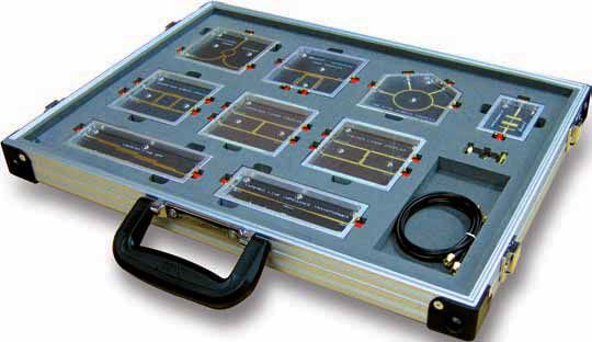
Product name: RF Design Technology Trainer Model: YRFDT-1000 Feature
1. Helps users acquire basic RF circuit designing skills.
2. Helps users acquire RF module manufacturing skills.
3. Provides RF circuit measuring practices.
4. Provides chip components' value measuring practices in high frequency band.
Specification Frequency Band: 20[Mhz] ~ 2[GHz] Impedance: 50[Ω] Substrate material: FR-4 PCB thickness: 0.8[mm] Dielectric constant: 4.4 Operating Temperature: -20℃ ~ 50℃ Relative Humidity: 0% ~ 95%
Training Contents Chapter 1. Port Extension Chapter 2. Measuring Chip Impedance Chapter 3. Microstrip stub Chapter 4. RF choke Chapter 5. Impedance Matching 1 (using lumped element L, C) Chapter 6. Impedance matching 2 (using a converter) Chapter 7. Impedance matching 3 (using stub matching) Chapter 8. Impedance matching 4 (using L and C loaded on transmission line) Chapter 9. LC low pass filter Chapter 10. LC bandpass filter Chapter 11. Monopole Antenna Chapter 12. Microstrip Monopole Antenna Chapter 13. Microstrip Patch Antenna 1 Chapter 14. Microstrip Patch Antenna 2 Chapter 15. Microstrip Patch Antenna 3
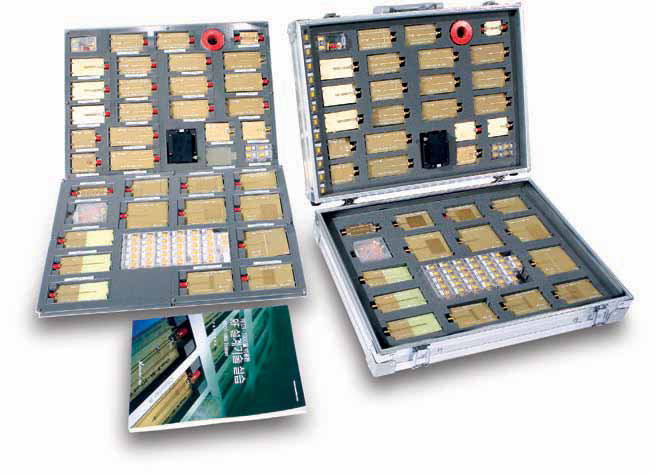
Product name: Microwave Experiment Kit Model: YMW-1000
Specification Frequency : 2.0[GHz] ~ 2.4[GHz] Impedance: 50[ohm] Connecting Loss: 0.3[dB] Substrate material: Teflon PCB thickness: 0.787[mm] Dielectric Constant: 2.5
Training Contents Chapter 1. Microwave Experiment Kit Overview Chapter 2. Tapered Line Impedance Transformer Chapter 3. Wilkinson Power Divider Chapter 4. Quadrature Hybrid Coupler Chapter 5. Coupled Line Directional Coupler Chapter 6. Folded Lange Coupler Chapter 7. Unfolded Lange Coupler Chapter 8. 180°£ Hybrid Chapter 9. Stepped Impedance Low Pass Filter Chapter 10. Coupled Line Band Pass Filter
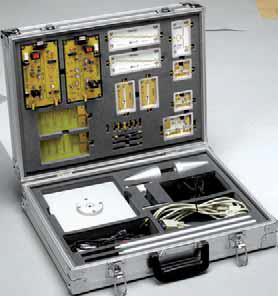
Product name: Microwave Communication Trainer(2.4GHz) Model: YMW-2000 Feature
■ Allowing students to train themselves about Experiment in microwave components design and manufacturing & Measurement applying microstrip line theory and microwave device design theory. For these experiment, standard devices and Specification & documents are supplied with software program as reference. Specification Frequency Band: 2,4[GHz] ~ 2.5[GHz] Modulation: FSK Bit rate: 4800 ~ 14400[bps] Output power: + 4.5 [dBm] Max Impedence: 50 [ohm] PCB thickness: 0.508 [mm] Dielectric constant: 3.38
Training Contents Chapter 1. Introduction to Microwave Communication Trainer Chapter 2. FSK Modulator Chapter 3. RF Amplifier Chapter 4. Antenna Chapter 5. Low Noise Amplifier Chapter 6. Power Divider Chapter 7. Band Pass Filter Chapter 8. Detector Chapter 9. FSK Demodulator Chapter 10. Microwave Communication Experiments
Product name: Microwave Communication Trainer(5.8GHz) Model: YMW-5000 Feature
■ Allowing students to train themselves in microwave components design and manufacturing & measuring by using Passive and Active devices and program at 5.8GHz. For these experiment, standard devices and specification & documents are supplied with software program as reference. Specification Frequency Band: 5.75[GHz] ~ 5.85[GHz] Modulation: FSK Bit rate: 4800 ~ 14400[bps] Output power: + 4.5 [dBm] Max Impedence: 50 [ohm] Substrate material: TLY-5A-0200-CH/CH PCB thickness: 0.508 [mm] Dielectric constant: 2.17
Training Contents Chapter 1. Introduction to Microwave Communication Trainer Chapter 2. FSK Modulator Chapter 3. RF Amplifier Chapter 4. Antenna Chapter 5. Low Noise Amplifier Chapter 6. Power Divider Chapter 7. Band Pass Filter Chapter 8. Detector Chapter 9. FSK Demodulator Chapter 10. Microwave Communication Experiments
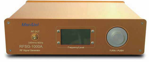
Product name: RF Signal Generator Model: YRFSG-1000A Feature
■ Signal Generator has wide frequency band.
■ Output frequency and power level is controlled by knob.
■ MENU is displayed in Graphic LCD(128x64 dots). Specification Frequency: 0.1~ 6.0 GHz (Variable 1MHz Step) Output Power: -10 ~ +5 dBm, 1dBm Step Oscillation: PLL frequency synthesized Impedence: 50 [ohm] Supply Power: AC Max 264V Harmonics: 100~2000MHz ≤ -30dBc 2000~3000 MHz ≤ -22dBc 3000~5000 MHz ≤ -25dBc 5000~6000 MHz ≤ -30dBc Sub-harmonic: 4401~6000 MHz ≤ -20dBc
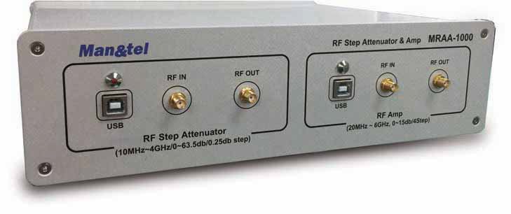
Product name: RF Attenuator / Amplifier Training Kit Model: YMRAA-1000 Feature
■ To amplify or attenuate the frequency in the high frequency bands. Specification 1) Attenuated Part Frequency Range: 10~4000Mhz Max Input RF Power: +33dBm(2W) VSWR: 1.65(Max) Attenuator: 0~63.5dB(0.25 step) Setting Time: 100us Insertion Loss: 10~100MHz = -2.0dB 101~500 MHz = -2.2dB 501~3000 MHz = -2.9dB 3001~4000 MHz = -3.8dB Connector: Power / Interface = USB FR IN / OUT = SMA (F) 2) Amplified Part
Frequency Range: 20MHz~6000MHz, 5MHz step Gain: 5~25dB, 5dB step Accuracy: ±0.5dB (SMA-SMA) Gain BW: 50MHz (Calibrated) Power/Interface USB
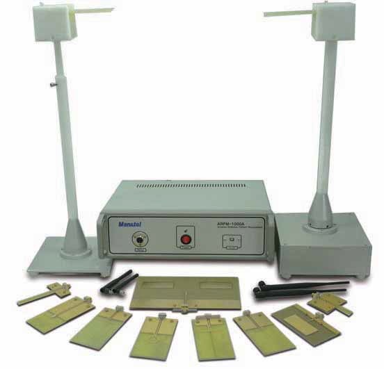
Product name: Antenna Training System Model: YARPM-1000A Feature
■ RF signal generator is not included in ARPM-1000A
■ Signal generator should be prepared as external equipment.
■ Practice of Antenna characteristics is possible
■ Suitable for training Antenna designing, manufacturing, measuring.
■ Radiation pattern can be measured without extra equipment
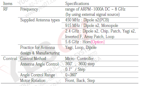
■ Auto calibration function is used to set maximum input power position Specification
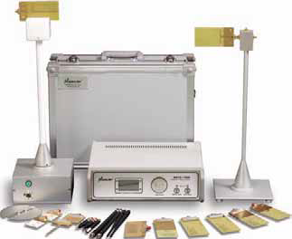
Product name: Antenna Training System Model: YMATS-1000A Feature
■ RF signal generator is included
■ Practice for Antenna characteristics is possible
■ Signal frequency and Output power is variable.
■ Suitable for training Antenna design, manufacturing, measurement.
■ Practice is possible without extra measuring equipment
■ Auto calibration is included to set maximum input power position.
Specification Frequency: Variable in 100MHz~6GHz, Output power: -10dBm ~ +5dBm AGC: 25 [dB] Oscillation: PLL frequency synthesized Impedance: 50 [ohm] Supplied Antenna Types: - 450 MHz : Dipole x2(PCB) - 915 MHz : Dipole x2, Monopole - 2.4 GHz : Dipole x2, Chip, Patch, Yagi x2, Inverted F, Array Patch, Loop - 5.6 GHz : Horn[Option], 5.8GHz Yagi×2 Practice for Antenna Manufacturing: Yagi, Loop, Dipole Control Method: Micro-Controller Antenna Angle Control: - 360˚, 3600 step - 0.1˚ / Step Motor Rotation: Front, Back, Step
Training Contents Chapter 1. Introduction of system Chapter 2. Program Installation and Instruction Chapter 3. Practice for Dipole antenna Chapter 4. Practice for Yagi antenna Chapter 5. Practice for Monopole antenna Chapter 6. Practice for Loop antenna Chapter 7. Practice for Ceramic Chip antenna Chapter 8. Practice for Inverted F antenna Chapter 9. Practice for Patch and Array Patch antenna Chapter 10. Practice for antenna Impedance matching Chapter 11. Practice for antenna Gain measurement Chapter 12. Manufacture of Dipole antenna Chapter 13. Manufacture of Loop antenna Chapter 14. Manufacture of Yagi antenna
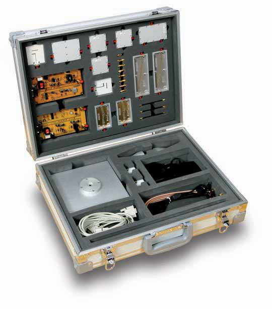
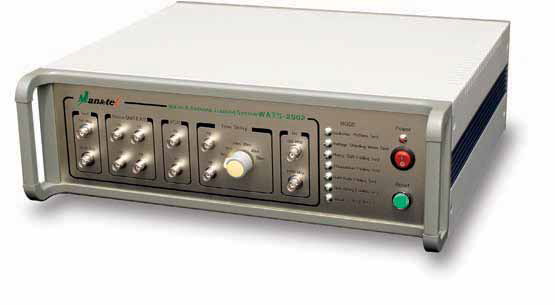
Product name: Wave and Antenna Training System Model: YWATS-2002 Feature
■ Most experiment is possible without extra measuring equipment.
■ Antenna characteristics measurement.
■ Mobile communication propagation experiment.
■ Propagation modeling & Loss Simulation.
■ Auto Calibration.
■ User interface with GUI windows.
Specification Frequency: 914 [MHz] , 2.45 [GHz] Output Power: +4.5 [dBm] Max Local Oscillation: PLL Impedance: 50 [ohm] AGC Dynamic Range:[dB] IF: 21.7 [MHz] Antenna: Yagi, Chip, Dipole, Monopole, Loop, Patch, Invented F, Array Patch Control Method: Micro-controller Antenna Angle Control: - 360°, 400 steps - 0.9°/ steps Angle Control range: 0~360° Position Calibration: Auto Calibration Motor Rotation: Front, Back, Step
Training Contents Chapter 1. Introduction of WATS-2002 Chapter 2. Program Installation and Instruction Chapter 3. Dipole Antenna Characteristics Experiment Chapter 4. Yagi Antenna Characteristics Experiment Chapter 5. Monopole Antenna Characteristics Experiment Chapter 6. Loop Antenna Characteristics Experiment Chapter 7. Ceramic Chip Antenna Characteristics Experiment Chapter 8. Inverted F Antenna Characteristics Experiment Chapter 9. Patch and Array Patch Antenna Characteristics Experiment Chapter 10. Dipole and Yagi Antenna Production and Analysis Experiment Chapter 11. Loop Antenna Production and Analysis Experiment Chapter 12. Phase Delay Experiment Chapter 13. Power Attenuation Characteristic Experiment Chapter 14. Multi-Path Fading Experiment Chapter 15. Time Delay and Doppler Effect Experiment Chapter 16. Standing Wave Experiment Chapter 17. Propagation Modeling and Propagation Loss Experiment
